A tool established in display technology – the conoscope, from the Greek konos = cone and scopeo = to test – for examining the distribution of luminous intensity is experiencing new applications in the course of the spread of LIDAR sensors in advanced driver assistance systems and the necessary testing of these sensors. With conoscope lenses, a simultaneous measurement of the angular distribution is performed because each pixel coordinate of the camera can be assigned to an emission angle of the LIDAR. The applications of conoscopes in LIDAR testing range from ensuring the correct alignment of the transmitter and receiver unit, to a novel range testing concept without having to resort to several 100 m long measurement distances in end-of-line testing.
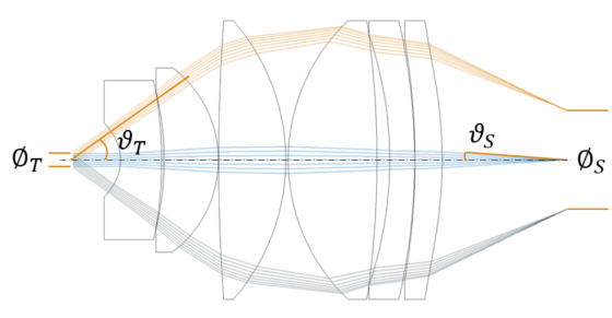
Conoscopes for angle measurement
From a small test area of diameter ∅T, the largest possible angular field of ±ϑT is imaged onto a sensor of size ∅S. The required entrance pupil for LIDAR testing is generally an order of magnitude larger than for liquid crystal display testing, but the angular range is not reduced by the same factor. Entrance pupil and angular range determine the physical quantity Étendue or also called acceptance. Without loss of light within the conoscope, this is a conserved quantity. When selecting possible sensors, it must be taken into account that the selection of a sensor size simultaneously determines the acceptance angle ϑS and thus the image-side numerical aperture as well as the complexity of the conoscope. Consequently, it can be said that the smaller the image sensor, the larger the numerical aperture and the more complex the required optical design. Take advantage of our expertise here and let us work with you to determine the ideal combination of lens and camera for your application.
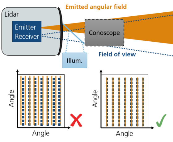
Emission angle test and transceiver alignment
In order to reliably detect small objects at a distance of more than 100 meters and to reliably differentiate between closely separated objects, it must be ensured that
- the transmitting unit spans a sufficient angular spectrum, e.g. a laser line of predetermined length and width, and
- transmitting and receiving units are optimally adjusted to each other, e.g. by overlapping the laser lines with a photodiode array.
Take advantage of our years of experience in designing complex optical systems as well as our expertise in developing lenses and get a conoscope with precise beam steering and minimal pupil aberration, ensuring that corresponding angles of the transmitter and receiver unit actually impinge on the camera at the same location.
Range testing rethought
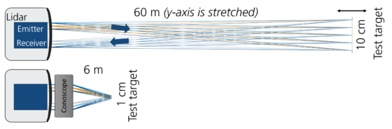
The verification of range sensitivity in end-of-line testing with a free-beam setup usually requires setups with unwieldy dimensions, for example with a 10 cm target at 60 m distance. With the diffuse light backscattered from the target, the signal-to-noise ratios of the sensor are measured and from this the range sensitivity is determined.
Our innovative concept based on our conoscope lenses aims at a reduction of the range test. For example, depending on the focal length of the conoscope, a 1 cm (instead of 10 cm) target can now be placed at a distance of only 6 m (instead of 60 m).
Contact us and discuss your ranging test with us. We are sure to find an efficient solution together based on our conoscope technology.
You can reach Dr. Markus Rollinger at | +49 6201 650 40-16.